Key Takeaways
- Electromagnetic Wave Propagation & Link Budget
- Backscatter Modulation Principle
- Tag Chip Architecture
01Electromagnetic Wave Propagation & Link Budget
UHF RFID operates in the 860-960 MHz band, corresponding to wavelengths of ~0.31-0.35 m. The reader antenna's radiated wave follows the Friis free-space path loss equation: PL = (4πd/λ)². At 1 m and 915 MHz, path loss is ~31.7 dB; at 6 m it climbs to 47.3 dB. This equation is the starting point for optimising read range — every doubling of distance adds 6 dB of loss, equivalent to a four-fold attenuation of the readable backscatter signal.
Real environments must also account for multipath, polarisation mismatch, antenna gain and feed-line loss. A typical fixed reader transmits 30 dBm (1 W) with 6 dBi antenna gain and a tag sensitivity of -18 dBm. The forward link budget reaches ~7-10 m; the reverse link, due to tag reflection efficiency of only -10 to -15 dB, often becomes the bottleneck. This is why tag antenna design and chip sensitivity are the decisive factors in UHF system performance.
- Friis equation: PL(dB) = 20log₁₀(4πd/λ)
- 915 MHz free-space 1 m loss ≈ 31.7 dB
- Each doubling of distance adds 6 dB loss
- Tag reflection efficiency only -10 to -15 dB, reverse link is the bottleneck
02Backscatter Modulation Principle
A passive UHF tag has no local oscillator — it modulates the carrier emitted by the reader by switching the impedance at the antenna port, a mechanism called backscatter modulation. The chip switches between two impedance states (typically matched and mismatched) to produce amplitude-shift keying (ASK). The switching rate defines the subcarrier frequency of the returned data, typically 40-640 kHz under the Gen2 protocol.
The Gen2 protocol defines four encoding schemes: FM0, Miller-2/4/8. FM0 is the fastest but least noise-resistant; Miller encoding improves multipath resistance through cyclic switching at the cost of data rate. In metal-dense warehouse environments, Miller-4 is typically the best rate-reliability trade-off. The reader dynamically switches encoding via the TRext, DR and M parameters in the Query frame — the core mechanism of Gen2 link adaptation.
- Passive tags have no oscillator; they backscatter by switching impedance
- ASK modulation: matched/mismatched impedance states
- Gen2 encodings: FM0, Miller-2/4/8
- Miller-4 preferred in metal-dense environments
03Tag Chip Architecture
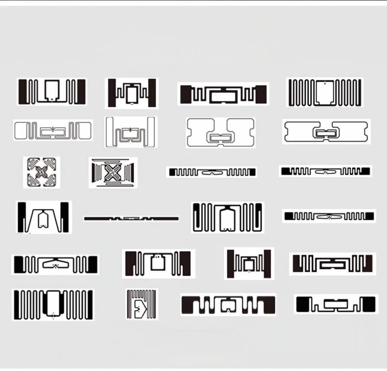
A UHF tag chip consists of four parts: the RF front-end (rectifier, limiter, demodulator), the digital baseband (state machine, CRC, PRNG), the memory (four banks — EPC/TID/User/Reserved), and power management (charge pump, regulator). The rectifier converts received RF power of -10 to +10 dBm into ~1.2 V DC to drive the digital circuitry. Advanced chips such as the Impinj M740 still operate at -23 dBm, a ~5 dB sensitivity improvement over the previous generation.
- Rectifier: RF power → 1.2 V DC, ~30-40% conversion efficiency
- PRNG: 16-bit pseudo-random number generator for anti-collision slot allocation
- Four memory banks: EPC(96-496b), TID(48-128b), User(0-512b), Reserved(64b)
- Impinj M740 sensitivity -23 dBm, ~5 dB better than prior generation
04Anti-Collision Algorithm & the Q-Algorithm
UHF RFID uses a slotted-ALOHA-based anti-collision mechanism. The reader issues a Query frame carrying the Q parameter (0-15); tags pick a random slot among 2^Q via PRNG to respond. On collision, the reader dynamically adjusts Q based on collision rate: more collisions raise Q (more slots), more idle slots lower Q (higher throughput). This adaptive process is the Q-algorithm — the core of Gen2 high-density reading.
In field tests, a 4-antenna fixed reader reads 500-700 unique tags/sec at Q=4 and 1,000+ at Q=6 with higher latency. SpidersRFID middleware auto-tunes the initial Q per scenario: retail cycle-count Q=4, logistics tunnel Q=5, dense warehouse Q=6. Understanding the Q-algorithm is critical to diagnosing "read-rate shortfall" — a wrong Q can slash throughput by more than 50%.
- Slotted ALOHA: tags choose a random slot among 2^Q to reply
- Q=4: 500-700 tags/s; Q=6: 1000+ tags/s
- Retail Q=4, logistics tunnel Q=5, dense warehouse Q=6
- Wrong Q can slash throughput by >50%